This product is suitable for lead-acid battery, not for Lithium Battery.
RS485 Battery Management System BMS can measure up to 24 batteries, and the type of single cell is divided into 2V, 6V and 12V.
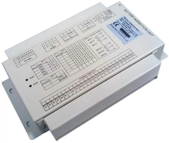
The basic function of the WB7660QB-24Z battery inspector(RS485 Battery Management System BMS) is to detect the single cell voltage of the battery group and the total voltage at both ends of the battery group. It is mainly used to monitor the voltage of the battery group in the DC power supply of the telecommunication machine room and the communication base station. The internal measurement circuit uses high precision A/D to detect the battery voltage in each section.
Each measurement port is isolated by the photoelectric isolator and the inner core circuit, and the battery voltage input port is connected with the protective resistance, which ensures the good safety of the battery inspector and the high precision of the measured data. Using RS485 communication interface to output data, RS485 Battery Management System BMS can be directly connected with the monitoring module of the DC screen manufacturer.
Specifications:
1. Number of detection channels: battery: 24 knots; current: 1 channel (outside with Hall sensor);
temperature: 2 channels (outside with temperature sensor);
2. Input specifications: voltage: 2V, 6V, 12V optional; current: 0 ~ ± 50A (default);
temperature: -20 ° C ~ +85 ° C;
3. Basic error: voltage: 0.5% (10% ~ 120% rating); current: 1% (1% ~ 120% rating);
temperature: ± 1.5 ° C (-10 ° C ~ +85 ° C: ± 0.5 ° C);
4. Response time: <3s (about 100ms to detect a battery);
5. Communication method: RS485 serial communication;
6. Communication node: ≤ 32 points;
7. Baud rate: Under the Modbus-RTU protocol, the baud rate can be set from 2400 to 19200 bps;
8. Power supply: DC 43 ~ 300V, AC 90V ~ 250V or DC 12 ~ 24V (special customizable);
9. Product power consumption: <3W (including matching current sensor, temperature sensor);
10. Safety: in accordance with IEC60950-1:2005/EN60950-1:2006;
11. Working environment: temperature: -20 ° C ~ +65 ° C;
relative humidity: 5% ~ 95%, no corrosion and condensation occasions;
12. Storage environment: temperature: -40 ° C ~ +70 ° C;
relative humidity: 5% ~ 95%, no corrosion and condensation occasions;
13. Product weight: about 1kg.
Product Shape and Installation Size

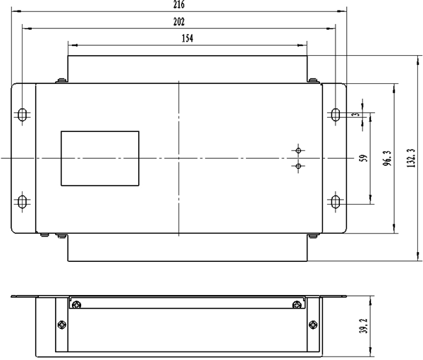
Figure 1. The Shape of Battery Inspector and Size Diagram of Installation (unit: mm)
The Position and Definition of the Connecting Terminals

Figure 2. Product Connecting Terminals Drawing (If there is a difference from the actual product, please take the material object as accurate)
Table 1. Definition of the Battery Inspector Connecting Terminals
Port Name | Indicia | Definition | Remarks |
J1 Power input port | L/- | AC power supply input phase line / DC power supply input negative pole | AC and DC common terminal, please pay attention to the voltage level when using, so as not to damage the product. |
N/+ | AC power supply input midline / DC power supply input positive pole | ||
PE | Protective grounding | ||
J2 Current detection port | +12V | Positive pole of the current sensor power supply (output) | Equipped with Hall sensor |
GND | Grounding of the current sensor power supply (output) | ||
ICT | The current sensor 1 input | ||
J3 Temperature detection port | +3.3V | Positive pole of the temperature sensor power supply (output) | Equipped with temperature sensor |
GND | Grounding of the temperature sensor power supply (output) | ||
T1 | The temperature sensor 1 input | ||
T2 | The temperature sensor 2 input | ||
J4 RS485 interface | A | RS485A | Communication with background or monitoring module, double connection port, convenient cascade |
B | RS485B | ||
J5 Battery detection port | BAT1+~ BAT24+ | Positive pole from first section battery to twenty-fourth section battery | If the battery connection polarity is wrong, the value of the detected battery voltage is abnormal |
BAT24- | Negative pole of the battery pack (or negative pole of the twenty-fourth section battery) | ||
Dial switch | It is used to set up communication protocol, baud rate and the address of battery inspector. Specific settings see "Dial Code Switch Settings". | ||
Dial Code Switch Settings
Figure 3. Position Diagram of Dialing Switch | The dial switch 1' ~ 2' bits are used to set the baud rate, 3' bits are used to select the communication protocol. 4' ~ 8' bits are used to set up the binary communication address of the inspector. Switch to "ON" to indicate that the setting is 0. The details are set as follows. |
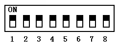
Table 2. Baud Rate Settings
1' Bits | 2' Bits | Baud Rate |
ON | ON | 2400BPS |
ON | OFF | 4800BPS |
OFF | ON | 9600BPS |
OFF | OFF | 19.2KBPS |
Table 3. Sensor Address Settings
4' Bits | 5' Bits | 6' Bits | 7' Bits | 8' Bits | Sensor Address |
ON | ON | ON | ON | ON | 0+112 |
ON | ON | ON | ON | OFF | 1+112 |
ON | ON | ON | OFF | ON | 2+112 |
ON | ON | ON | OFF | OFF | 3+112 |
… | … | … | … | … | … |
OFF | OFF | OFF | OFF | OFF | 31+112 |
Table 4. Protocol Selection
3' Bits | Communication Protocol |
ON | Emerson monitoring protocol |
OFF | MODBUS-RTU |
The battery inspector's factory address is 112, and the baud rate is 9600bps. Whether the Emerson Monitoring Protocol or the MODBUS-RTU Protocol is chosen, the address of the battery inspector is 112 + address of setting of dial switch. If you choose the Emerson Monitoring Protocol, the baud rate is fixed to 9600bps; if you choose the MODBUS-RTU Protocol, the baud rate is set according to the setting in Table 3.
Advantages: 27000 square meters non-dust workshop, 30 years’ experience, 6 years' application in high speed railway, ISO, EMC, ETC certificated. | Applications: Inverter and converter; Photovoltaic combiner box, battery management system; Charging pile; Wind farm monitoring, power feedback control. |
Hot Tags: (For Lead-acid Battery) RS485 Battery Management System BMS, China, suppliers, factory, price