

Interfacing an AC voltage sensor with an analog output to a Programmable Logic Controller (PLC) is a crucial process in many industrial applications. As a supplier of AC Voltage Sensors With Analog Output, I have witnessed firsthand the importance of this connection in ensuring accurate monitoring and control of electrical systems. In this blog post, I will guide you through the steps of interfacing an AC voltage sensor with an analog output to a PLC, providing you with the knowledge and tools you need to successfully implement this setup.
Understanding the Basics
Before we dive into the process of interfacing an AC voltage sensor with a PLC, it's important to understand the basic components involved. An AC voltage sensor with an analog output is designed to measure the alternating current (AC) voltage in an electrical circuit and convert it into an analog signal. This analog signal can then be used by a PLC to monitor and control the voltage levels in the circuit.
A PLC, on the other hand, is a digital computer that is used to control industrial processes. It is programmed to execute specific tasks based on input signals received from sensors and other devices. By interfacing an AC voltage sensor with a PLC, you can use the PLC to monitor the voltage levels in the circuit and take appropriate actions based on the readings.
Step 1: Selecting the Right AC Voltage Sensor
The first step in interfacing an AC voltage sensor with a PLC is to select the right sensor for your application. There are several factors to consider when choosing an AC voltage sensor, including the voltage range, accuracy, and output signal type.

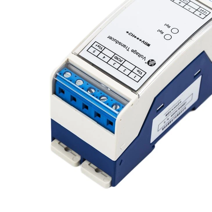
- Voltage Range: The voltage range of the sensor should match the voltage levels in the circuit you are monitoring. For example, if you are monitoring a circuit with a voltage range of 0-150V, you should choose a sensor with a corresponding voltage range. You can find a suitable sensor with a voltage range of 0-150V and an output of 4-20mA here.
- Accuracy: The accuracy of the sensor is another important factor to consider. A more accurate sensor will provide more precise readings, which is crucial for applications that require high levels of control.
- Output Signal Type: The output signal type of the sensor should be compatible with the input requirements of the PLC. Most PLCs accept analog signals in the form of voltage or current. Make sure to choose a sensor with an output signal type that is compatible with your PLC. For example, a Voltage Transmitter 4-20mA for Controlling Industrial is a popular choice for interfacing with PLCs.
Step 2: Wiring the AC Voltage Sensor to the PLC
Once you have selected the right AC voltage sensor for your application, the next step is to wire the sensor to the PLC. The wiring process will depend on the specific sensor and PLC you are using, but the general steps are as follows:
- Identify the Input Terminals: Locate the input terminals on the PLC that are designed to accept analog signals. These terminals are usually labeled as "AI" (Analog Input).
- Connect the Sensor Output: Connect the output of the AC voltage sensor to the input terminals on the PLC. Make sure to follow the wiring diagram provided by the sensor manufacturer to ensure proper connection.
- Provide Power Supply: Most AC voltage sensors require a power supply to operate. Connect the power supply to the sensor according to the manufacturer's instructions.
- Grounding: Proper grounding is essential for the safety and accuracy of the system. Make sure to connect the ground wire of the sensor and the PLC to a common ground.
Step 3: Configuring the PLC
After wiring the AC voltage sensor to the PLC, the next step is to configure the PLC to read the analog signal from the sensor. The configuration process will depend on the specific PLC you are using, but the general steps are as follows:
- Access the PLC Programming Software: Open the programming software for your PLC and connect to the PLC.
- Create a New Project: Create a new project in the programming software and select the appropriate PLC model.
- Configure the Analog Input Module: Locate the analog input module in the PLC configuration and configure it to accept the analog signal from the AC voltage sensor. This may involve setting the input range, scaling, and other parameters.
- Create a Program: Write a program in the PLC programming language to read the analog signal from the sensor and perform the desired actions based on the readings. For example, you may want to set up an alarm if the voltage level exceeds a certain threshold.
- Download the Program: Once you have completed the programming, download the program to the PLC.
Step 4: Testing and Calibration
After configuring the PLC, the next step is to test and calibrate the system to ensure accurate readings. The testing and calibration process will depend on the specific sensor and PLC you are using, but the general steps are as follows:
- Power On the System: Turn on the power supply to the AC voltage sensor and the PLC.
- Check the Readings: Use a multimeter or other measuring device to check the voltage levels in the circuit. Compare the readings from the multimeter with the readings from the PLC to ensure they are consistent.
- Calibrate the Sensor: If the readings from the PLC are not consistent with the readings from the multimeter, you may need to calibrate the sensor. Follow the calibration instructions provided by the sensor manufacturer to adjust the sensor output.
- Test the System: Once the sensor is calibrated, test the system by changing the voltage levels in the circuit and observing the response of the PLC. Make sure the PLC is able to accurately monitor and control the voltage levels in the circuit.
Step 5: Maintenance and Troubleshooting
After the system is up and running, it's important to perform regular maintenance and troubleshooting to ensure its continued operation. The maintenance and troubleshooting process will depend on the specific sensor and PLC you are using, but the general steps are as follows:
- Regular Inspections: Perform regular inspections of the AC voltage sensor and the PLC to check for any signs of damage or wear. Replace any damaged components as needed.
- Cleaning: Keep the AC voltage sensor and the PLC clean to prevent dust and debris from accumulating. Use a soft cloth or compressed air to clean the components.
- Firmware Updates: Check for firmware updates for the PLC and the AC voltage sensor regularly. Install any updates as needed to ensure the system is running the latest software.
- Troubleshooting: If you encounter any problems with the system, refer to the troubleshooting guide provided by the sensor and PLC manufacturers. Use a multimeter or other measuring device to diagnose the problem and take appropriate actions to fix it.
Conclusion
Interfacing an AC voltage sensor with an analog output to a PLC is a complex process that requires careful planning and execution. By following the steps outlined in this blog post, you can successfully interface an AC voltage sensor with a PLC and ensure accurate monitoring and control of electrical systems.
As a supplier of AC Voltage Sensors With Analog Output, I am committed to providing high-quality products and excellent customer service. If you have any questions or need assistance with interfacing an AC voltage sensor with a PLC, please don't hesitate to contact me. I will be happy to help you find the right solution for your application.
References
- Manufacturer's documentation for the AC voltage sensor
- Manufacturer's documentation for the PLC
- Electrical engineering textbooks and resources