

Yo, folks! As a supplier of AC Voltage Sensors, I've been in the thick of exploring how the waveform of AC voltage impacts sensor measurements. It's a wild ride full of technical quirks and real - world implications. Let's dig in!
First off, AC voltage is far from being a simple, steady signal. The waveform of AC voltage can take on various shapes. The most common one is the sine wave, which is the standard in most power systems. But in reality, waveforms can be distorted due to a bunch of factors. For example, non - linear loads like computers, electronic ballasts, and adjustable speed drives introduce harmonics into the power system. These harmonics can cause the waveform to deviate from the pure sine shape.
Now, how does this affect our sensors? Well, let's start with the accuracy of measurement. Most of our Voltage Sensor 30V are designed to measure based on a standard sine wave assumption. When the waveform is sinusoidal, the sensors can accurately calculate root - mean - square (RMS) values, which are crucial for determining the effective power and voltage levels. But when the waveform is distorted, the RMS value calculated by the sensor might not accurately represent the real - world situation.
Let's take a closer look. A distorted waveform has additional frequency components (harmonics) on top of the fundamental frequency. Our sensors, especially the ones with a narrow frequency response, might not be able to pick up these higher - order harmonics properly. This can lead to an under - or over - estimation of the voltage. For instance, if a sensor is calibrated for a pure sine wave and there are significant third - order harmonics in the actual waveform, the measured voltage might be lower than the true effective voltage.

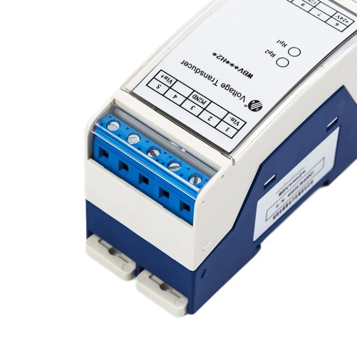
Another aspect is the response time of the sensors. In a normal sine wave situation, sensors can quickly adjust to the changes in voltage. However, when dealing with distorted waveforms, the sudden spikes and dips caused by harmonics can catch the sensor off - guard. Some of our 4 - 20mA Voltage Sensor 0 - 10V Output are built to have a relatively fast response time, but extreme waveform distortion can still pose challenges. If the sensor can't respond fast enough, it may miss important voltage changes, leading to inaccurate readings.
The type of sensor also plays a role. For example, our 500V Input Electrical Isolation Transducer are designed to isolate the measuring circuit from the high - voltage source. While they offer good protection, they may have a more complex response to distorted waveforms. These transducers often rely on certain filtering mechanisms to process the input signal. If the waveform distortion is severe, the filter may not be able to separate the fundamental frequency from the harmonics effectively, resulting in erroneous measurements.
Now, what about Voltage Transducer 60V? These transducers are commonly used in various industrial applications. In industrial settings, the power supply is often more likely to have distorted waveforms due to the large number of non - linear loads. The performance of these transducers can be affected by the waveform in terms of both accuracy and long - term stability. A constantly fluctuating and distorted waveform can cause stress on the internal components of the transducer, potentially leading to premature wear and tear.
Our Arduino Voltage Sensor 60V is popular among hobbyists and DIY enthusiasts. These sensors are relatively simple in design and are calibrated for standard sine waves. When used in an environment with distorted waveforms, they may give inaccurate readings. Since Arduino projects often rely on accurate voltage measurements for proper functioning, this can be a real problem. For example, if you're building an Arduino - based power monitoring system and the voltage sensor gives incorrect readings due to waveform distortion, the entire system may malfunction.
So, what can we do about it? Well, as a supplier, we're constantly working on improving our sensors. We're developing sensors with wider frequency responses to better handle distorted waveforms. We're also enhancing the filtering algorithms inside the sensors to more accurately separate the fundamental frequency from harmonics.
If you're in the market for AC voltage sensors, it's important to consider the waveform characteristics of your application. If you're dealing with a relatively clean sine wave, our standard sensors should work just fine. But if you expect significant waveform distortion, you might want to look into our advanced models that are designed to handle such situations.
We're here to offer you the best solutions for your voltage - sensing needs. Whether you're a large industrial company or a small - scale DIYer, we've got sensors that can fit your requirements. If you've got questions or are interested in purchasing our products, don't hesitate to reach out. Let's start a conversation and figure out the best sensor for your specific project.
References
- Electrical Engineering: Principles and Applications by Allan R. Hambley
- Power System Harmonics and Passive Filter Design by A. Chandra and M. Venturini